星期二, 12月 23, 2014

【自由軟體】 Dia 流程圖軟體

<<軟體說明>>
Dia 被設計成與商業版的視窗軟體 Visio 十分類似。 它可以被用來繪製不同種類的流程圖。在這一版中,也支援了 UML 靜態結構流程圖和網路流程圖。目前可以讀取和儲存流程圖到自定的檔案格式和匯出成 postscript, 並且內建了一些常用的圖示,如網路架構及流程圖等。
<<體特色>>
1.輕易繪製不同種類的流程圖
2.支援 UML 靜態結構流程圖和網路流程圖的繪製。
3.讀取和儲存流程圖到自定的檔案格式
4.能匯出成 postscript
5.內建許多常用的圖示
<<體畫面>>


<<體下載>>

<<體安裝>>
Step1. 安裝GTK2:請執行gtk+-2.8.18-setup-1.zip。
Step2. 安裝程式:請執行dia-setup-0.95-1.zip。

注意事項:
Question: 在Windows 環境下安裝完畢後,方塊的中文輸入或標籤不能顯示中文?
Answer: 只要在功能表裏選擇輸入法->簡易不能用默認的 系統(Windows IME)。

參考資料:
1. http://ossacc.moe.edu.tw/modules/tinyd1/index.php?id=36
2. https://allen501pc.wordpress.com/2010/09/08/dia-0-97-%E8%BC%B8%E5%85%A5%E4%B8%AD%E6%96%87%E7%9A%84%E6%96%B9%E6%B3%95/ 

星期一, 11月 24, 2014

Android 手機不見的定位追蹤

利用 Google 地圖行動版 (https://www.google.com/intl/zh-Hant/maps/about/explore/mobile/ )的【Google 設定中的位置資訊】https://support.google.com/gmm/answer/3118687?hl=zh-Hant 來檢索Android 行動裝置的【定位】資料,已掌握先前的手機位置。如果你目前手機沒有開定位,它可沒有聰明到知道手機在哪裡,但是可以呼叫他一下。
1. 先設定你的裝置 【Google 設定】
2.   使用「帳戶紀錄」網站開啟或關閉定位紀錄

  1. 前往 google.com/settings/accounthistory
  2. 登入您要用來記錄位置的 Google 帳戶。
  3. 【帳戶紀錄】-- 選取 【您造訪過的地方】 卡片--【管理紀錄】。
  4. 根據您目前的設定選取 [啟用] 或 [停用]
  5. 詳閱通知內容,然後選取按鈕來啟用或停用定位紀錄。


參考資料:
1. https://support.google.com/gmm/answer/3118687?hl=zh-Hant

星期四, 11月 20, 2014

看盤軟體出現 Java 錯誤

Polaris 點金靈看盤軟體出現 Java 錯誤

修改 Java 軟體的設定--【開始】--【JAVA】--【Configure JAVA】--【Java Plug-in】的【啟用新一代 Java Plug-in(需要重新啟動瀏覽器】,不要勾選。

點選【停用】
後續,點選【確定】即可,再將瀏覽器或看盤軟體重新啟用,如果不確定者重新開啟電腦看看。

注意事項:
1. Java 7 更新後,不要更新到 Java 8.


星期一, 11月 17, 2014

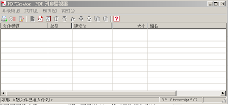
PDF Creator 1.3~1.7.3 列印出來是空白頁

問題:列印出來的文件是空白
1.7.3狀況下,資料夾路徑使用中文沒有問題,但是如果
  • 原始檔案 (要列印的檔案) 檔名包含中文,列印出來會是空白PDF
  • 輸出檔案 (列印出來的PDF) 檔名設定成中文,按下儲存按鈕後會整個消失,什麼事也沒發生 (沒有列印)

原因:無法讀取中文檔名

解法1:把原文件(.doc / .docx / .xls / .xlsx ...)的檔名改成英文數字,輸出PDF的檔名也設定成英文數字,重新列印一切正常。

解法2:(謝謝網友mt-tp-tw留言) 以下方法的原始出處: http://mt-tp-tw.blogspot.tw/2013/09/pdfcreator-v171.html
覺得這解法很棒~! 因為是使用原程式設計者的檔案而非改檔,被植入木馬程式的機率較低
P.S. 但這方法也只能讓原始檔案能使用中文檔名,輸出檔案還是必須設定成英文數字才能正常輸出
  1. ***作法為*****
1. 打開PDFCreator的主程式 (列印監視器)
  1. 2. 點選工具列的 [印表機→選項],開啟選項視窗
  2. 3. 點選 [動作→儲存前動作],把儲存前動作的勾選打勾
  3. 在「指令/程式碼」欄位點選 [...] 按鈕,到 PDFCreator安裝目錄\Scripts\RunProgramBeforeSaving 下找到 AddBookmarks.vbs 檔案並選擇
    舉例WIN7的預設安裝目錄是 C:\Program Files (x86)\PDFCreator\Scripts\RunProgramBeforeSaving
  4. 按下下方 [儲存] 按鈕,設定完成之後重新列印就OK了 (只需設定一次)


****

**** 目前使用此種方法是 OK的 ****

****
PS. 
1. 會強制安裝 OPERA 瀏覽器
2. 當重新開機後,word 列印不出 PDF 檔且瀏覽器的列印也一樣,所以只好降版到 1.2.3 版。


=======================================================================
參考資料來源: 
1. http://mt-tp-tw.blogspot.tw/2013/09/pdfcreator-v171.html
2. http://ccross.pixnet.net/blog/post/38445001-%5B轉檔%5D-pdf-creator-列印出來的文件是空白

星期三, 10月 29, 2014

筆電螢幕變黑問題

ASUS 筆電螢幕變黑,有可能是螢幕調整的太暗,可以按下 【Fn】+【F6*】,【*】為亮燈的圖示,以調整亮度。

星期二, 10月 21, 2014

當插入滑鼠時暫時關閉 ASUS PRO08 序列筆電的觸控板

筆電插入滑鼠時觸控板無法使用


ASUS 筆電在使用或打字時常常不經意的觸控到觸控板造成滑鼠會亂跑,為避免觸控板的影響,擬利用滑鼠控制而暫時停止觸控板。作法為
1.    首先,到官方網站下載驅動程式。例如ASUS PRO8BI 序列的筆電,原先認為是常用的 Synaptics 觸控程式,沒有想到沒有插入滑鼠後再暫停觸控板的功能,拔除即回復觸控板控制,顯然不方便。因此,下載asus 的另一觸控板軟體 ELAN smartpad 即出現有可控制的選項。
2.    設定方法為【控制台】--【滑鼠】


        勾選【當外部USB滑鼠插入時停用】


星期三, 10月 08, 2014

Lenovo G570 開圖檔會出現藍底白字 atikmpag.sys當機錯誤

昨天晚上讀取照片檔即出現藍底白字 atikmpag.sys 當機錯誤,經查 Google 網路許多軟體都說可以協助處理,但是安裝後才出現 "要錢",所以安裝後很後悔!

算了,我想可能也是 AMD Radeon 顯示卡問題,所以就在控制台的新增移除中動手,將出現有 "ATI....." 和 "AMD...."字言的驅動軟體移除,反正我也沒有要用甚麼 3D 或獨顯功能,殺無赦。

沒有想到,重新開機後可以讀取照片。真是的!!!!!

將 Bryton Cardio 40E 轉載到 Runkeeper 上


  1. 方法一: 利用 Bryton Cardio 官網的軟體(BrytonBridge2.exe),擷取手錶上的管理軟體【管理我的運動紀錄】的 .bpx (上傳官網用)與 .gpx 檔(上傳 Runkeeper 用)
  2. 方法二: 先將 Bryton Cardio 40E 的資料上傳到官網上,再利用官網上的轉檔功能,將原始的檔案 .bpx 轉為 Runkeeper 可讀取的  .gpx 或  .tcx 格式檔。
  3. 到 Runkeeper 網站 (http://runkeeper.com/) 利用 Facebook 身分登入,或是利用 Facebook 登入健身資料
  4. 上傳資料


參考資料:

  1. http://avril01307.pixnet.net/blog/post/30017808-%E8%B7%91%EF%BD%9C%E5%A6%82%E4%BD%95%E5%B0%87%E3%80%8Abryton-cardio-40%E3%80%8B%E8%B7%91%E6%AD%A5%E8%BB%8C%E8%B7%A1%E5%8C%AF%E5%85%A5%E5%88%B0-r

3D 免費軟體 Blender 與 SketchUp


星期二, 6月 10, 2014

Android 系統解除應用程式的偏好設定

由於手機應用程式安裝許多後,有遇到同類型的檔案,系統每次都會詢問是否要用此程式,有時我們會不經意的點選到 "永久"的選項,造成事後要修改不知道如何用?
可參考下列安小卓網站的資料做法:

圖文:安小卓
當您下載越來越多同類型的應用程式時,在開啟此類型的相關檔案或連結的時候,系統會主動問您要使用哪一個應用程式來開啟,例如下圖,在開啟網路上的影片時,程式會問您要使用網際網路、Chrome、YouTube哪一支應用程式來開啟,或是開啟相片檔案時,程式會問您要使用相片集或是ES圖像瀏覽器來開啟。
1 2
點選我們要使用的應用程式,再點選「永遠」或是「僅此一次」,點選「僅此一次」則下次遇到同類型的檔案或是連結會再重覆同樣的動作,相當的麻煩。因為建議點選永遠。如果要取消此預設程式的話,可以至「設定」>>「應用程式」點進您預設的那個應用程式,再點選「清除預設值」即可。
3 4
也可以點選「設定」「應用程式」「全部」功能選單裏的「重設應用程式偏好設定」這樣所有的預設程式都會清除掉。
5 6


資料來源: 
http://mcdulll.pixnet.net/blog/post/96548777-%5B%E6%95%99%E5%AD%B8%5D%E8%A8%AD%E5%AE%9A%E8%88%87%E8%A7%A3%E9%99%A4%E6%87%89%E7%94%A8%E7%A8%8B%E5%BC%8F%E5%81%8F%E5%A5%BD%E8%A8%AD%E5%AE%9A


星期二, 6月 03, 2014

利用 Windows Media 將 MP3 轉錄為 CD 撥放格式

1.放入空白光碟片,開啟 Windows Media Player 後,點擊[開啟[燒錄]索引標籤],切換到燒錄頁籤。


2.接下來,可以看到空白光碟的資訊。


3.再將要燒錄的 MP3 檔案,使用滑鼠拖拉到 Windows Media Player 指定位置。


4.確認燒錄的格式是要視選音訊 CD;點擊[其他燒錄選項]設定額外參數。


5.一切就緒後,點擊[開始燒錄]。


參考資料來源: http://key.chtouch.com/ContentView.aspx?P=2050

星期二, 5月 13, 2014

Ardublock 圖形化介面程式設計 Arduino

官方網站   http://blog.ardublock.com/
有中文介面,但是為簡體字,不習慣的話就用 English


下載與操作說明 http://blog.ardublock.com/engetting-started-ardublockzhardublock/


參考文章:
1. 圖形化程式ardublock, http://elesson.tc.edu.tw/md221/mod/page/view.php?id=2791
2. 安裝 ArduBlock 到 Arduino IDE,  http://wdpsestea.blogspot.tw/2014_01_01_archive.html

星期二, 4月 15, 2014

PDFCreator v1.7.1 版列印會出現空白問題

參考資料來源: http://mt-tp-tw.blogspot.tw/2013/09/pdfcreator-v171.html 感謝該作者協助處理我多年的困擾

以下藍色的字體即為解決方法 step by step:

  • 開啟 PDFCreator 程式(如下畫面)


  • 點選功能選單 "印表機" -> "選項 (Ctrl+O)",出現如下畫面
  • 點選螢光筆圈起來的部分 "動作" -> "儲存前動作" -> 勾選checkbox "儲存前動作" -> 在 "程式/指令碼" 下拉選單中,選取 "C:\Program Files\PDFCreator\Scripts\RunProgramBeforeSaving\AddBookmarks.vbs" -> 按右下角 "儲存(S)" 按鈕。
  • 完成! 打開 word 來印一份文件試試看囉!

星期四, 3月 27, 2014

Arduino 3鍵 Orange-skin 橘子皮電子琴

運用 Arduino 的 Capacitive Sensor 功能來製作 3 鍵電子琴,
感應平台使用橘子皮作為電子琴鍵


星期一, 3月 17, 2014

印表機出現 0x00000002 錯誤的解決方式

在 win 7 或 win 8 系統中印表機連線出現 0x0000002 錯誤,可以使用 [控制台]--[系統管理工具] -- [電腦管理]--[服務與應用程式] -- [服務] -- [print spooler],重新啟動

星期四, 3月 06, 2014

Arduino 測試電容量 Native Capacitive Sensors without additional Hardware

Native Capacitive Sensors without additional Hardware

You can create a touch-sensitive input on any of the Arduino's pins. It requires no special hardware, nevertheless a capacitor of 1nF is recommended in line with the pin to decouple 50Hz noises.
Connect a wire or some metallic plate to a pin.
The code works by setting the pin to ground, turning on the internal pull-up resistor, and measuring the time it takes for the pin to return to the HIGH state. If untouched readCapacitivePin returns a low value e.g. "1"; when touched it rises to about 5. By adding some comparision with a threshold you can make it a boolean key input.

DO NOT CONNECT ANY ACTIVE DRIVER TO THE USED PIN !

the pin is toggled to output mode to discharge the port, and if connected to a voltage source, will short circuit the pin, potentially damaging the Arduino and any hardware attached to the pin.
Original code by Mario Becker, Fraunhofer IGD, 2007http://www.igd.fhg.de/igd-a4
Updated by: Alan Chatham http://unojoy.tumblr.com
Updated by Paul Stoffregen: Replaced '328 specific code with portOutputRegister, etc for compatibility with Arduino Mega, Teensy, Sanguino and other boards
Gratuitous optimization to improve sensitivity by Casey Rodarmor.
Updated by Martin Renold: disable interrupts while measuring. This fixes the occasional too-low results.
Updated by InvScribe for Arduino Due.
With this function, you can call readCapacitivePin( pinNumber) and get a number from 0 to 17 corresponding to the level of capacitance on the pin - the number will be higher when you touch the pin.

// readCapacitivePin
//  Input: Arduino pin number
//  Output: A number, from 0 to 17 expressing
//  how much capacitance is on the pin
//  When you touch the pin, or whatever you have
//  attached to it, the number will get higher
#include "pins_arduino.h" // Arduino pre-1.0 needs this
uint8_t readCapacitivePin(int pinToMeasure) {
  // Variables used to translate from Arduino to AVR pin naming
  volatile uint8_t* port;
  volatile uint8_t* ddr;
  volatile uint8_t* pin;
  // Here we translate the input pin number from
  //  Arduino pin number to the AVR PORT, PIN, DDR,
  //  and which bit of those registers we care about.
  byte bitmask;
  port = portOutputRegister(digitalPinToPort(pinToMeasure));
  ddr = portModeRegister(digitalPinToPort(pinToMeasure));
  bitmask = digitalPinToBitMask(pinToMeasure);
  pin = portInputRegister(digitalPinToPort(pinToMeasure));
  // Discharge the pin first by setting it low and output
  *port &= ~(bitmask);
  *ddr  |= bitmask;
  delay(1);
  // Prevent the timer IRQ from disturbing our measurement
  noInterrupts();
  // Make the pin an input with the internal pull-up on
  *ddr &= ~(bitmask);
  *port |= bitmask;

  // Now see how long the pin to get pulled up. This manual unrolling of the loop
  // decreases the number of hardware cycles between each read of the pin,
  // thus increasing sensitivity.
  uint8_t cycles = 17;
       if (*pin & bitmask) { cycles =  0;}
  else if (*pin & bitmask) { cycles =  1;}
  else if (*pin & bitmask) { cycles =  2;}
  else if (*pin & bitmask) { cycles =  3;}
  else if (*pin & bitmask) { cycles =  4;}
  else if (*pin & bitmask) { cycles =  5;}
  else if (*pin & bitmask) { cycles =  6;}
  else if (*pin & bitmask) { cycles =  7;}
  else if (*pin & bitmask) { cycles =  8;}
  else if (*pin & bitmask) { cycles =  9;}
  else if (*pin & bitmask) { cycles = 10;}
  else if (*pin & bitmask) { cycles = 11;}
  else if (*pin & bitmask) { cycles = 12;}
  else if (*pin & bitmask) { cycles = 13;}
  else if (*pin & bitmask) { cycles = 14;}
  else if (*pin & bitmask) { cycles = 15;}
  else if (*pin & bitmask) { cycles = 16;}

  // End of timing-critical section
  interrupts();

  // Discharge the pin again by setting it low and output
  //  It's important to leave the pins low if you want to 
  //  be able to touch more than 1 sensor at a time - if
  //  the sensor is left pulled high, when you touch
  //  two sensors, your body will transfer the charge between
  //  sensors.
  *port &= ~(bitmask);
  *ddr  |= bitmask;

  return cycles;
}

For Arduino Due

// readCapacitivePin
//  Input: Arduino pin number
//  Output: A number, from 0 to 17 expressing
//  how much capacitance is on the pin
//  When you touch the pin, or whatever you have
//  attached to it, the number will get higher
uint8_t readCapacitivePin(int pinToMeasure) {
  pinMode(pinToMeasure, OUTPUT);
  digitalWrite(pinToMeasure, LOW);
  delay(1);
  // Prevent the timer IRQ from disturbing our measurement
  noInterrupts();
  // Make the pin an input with the internal pull-up on
  pinMode(pinToMeasure, INPUT_PULLUP);

  // Now see how long the pin to get pulled up. This manual unrolling of the loop
  // decreases the number of hardware cycles between each read of the pin,
  // thus increasing sensitivity.
  uint8_t cycles = 17;
       if (digitalRead(pinToMeasure)) { cycles =  0;}
  else if (digitalRead(pinToMeasure)) { cycles =  1;}
  else if (digitalRead(pinToMeasure)) { cycles =  2;}
  else if (digitalRead(pinToMeasure)) { cycles =  3;}
  else if (digitalRead(pinToMeasure)) { cycles =  4;}
  else if (digitalRead(pinToMeasure)) { cycles =  5;}
  else if (digitalRead(pinToMeasure)) { cycles =  6;}
  else if (digitalRead(pinToMeasure)) { cycles =  7;}
  else if (digitalRead(pinToMeasure)) { cycles =  8;}
  else if (digitalRead(pinToMeasure)) { cycles =  9;}
  else if (digitalRead(pinToMeasure)) { cycles = 10;}
  else if (digitalRead(pinToMeasure)) { cycles = 11;}
  else if (digitalRead(pinToMeasure)) { cycles = 12;}
  else if (digitalRead(pinToMeasure)) { cycles = 13;}
  else if (digitalRead(pinToMeasure)) { cycles = 14;}
  else if (digitalRead(pinToMeasure)) { cycles = 15;}
  else if (digitalRead(pinToMeasure)) { cycles = 16;}

  // End of timing-critical section
  interrupts();

  // Discharge the pin again by setting it low and output
  //  It's important to leave the pins low if you want to 
  //  be able to touch more than 1 sensor at a time - if
  //  the sensor is left pulled high, when you touch
  //  two sensors, your body will transfer the charge between
  //  sensors.
  digitalWrite(pinToMeasure, LOW);
  pinMode(pinToMeasure, OUTPUT);

  return cycles;
}


  • 資料來源:
http://playground.arduino.cc/Code/CapacitiveSensor 

知識學習--電容式觸控使用者介面

運用電容式觸控方法來製作 Paper Piano for Arduino

使用 Arduino 的 capacitive sensing library 功能,結合人體手指電容來驅動鉛筆畫製好的紙鍵盤。

How it works

The capacitiveSensor method toggles a microcontroller send pin to a new state and then waits for the receive pin to change to the same state as the send pin. A variable is incremented inside a while loop to time the receive pin's state change. The method then reports the variable's value, which is in arbitrary units.
The physical setup includes a medium to high value (100 kilohm - 50 megohm) resistor between the send pin and the receive (sensor) pin. The receive pin is the sensor terminal. A wire connected to this pin with a piece of foil at the end makes a good sensor. For many applications, a more useful range of values is obtained if the sensor is covered with paper, plastic, or another insulating material, so that users do not actually touch the metal foil. Research has shown that a small capacitor (100 pF) or so from sensor pin to ground improves stability and repeatability.
When the send pin changes state, it will eventually change the state of the receive pin. The delay between the send pin changing and the receive pin changing is determined by an RC time constant, defined by R * C, where R is the value of the resistor and C is the capacitance at the receive pin, plus any other capacitance (e.g. human body interaction) present at the sensor (receive) pin. Adding small capacitor (20 - 400 pF) in parallel with the body capacitance, is highly desirable too, as it stabilizes the sensed readings.

============================================================

知識學習--利用現有資源建構電容式觸控使用者介面

2011/12/08-DIGITIMES企劃  

若嵌入式系統設計中已包含微控制器,為了節省成本,也許可以使用電容式觸控介面取代按鈕和距離感測器(proximity sensor)。電容式觸控介面可保持產品的美觀且具有時尚風潮感;無需外嵌的零件特性,也方便設計人員將觸控系統密封起來,保護內部元件,並實現簡潔俐落的控制面板。即使大多數嵌入式系統中的微控制器已包含用來實現電容式觸控感測功能的零件、例如距離感測器和觸控按鈕;但設計人員仍未能加以善用並實現電容式觸控感測介面。本文將提供下列幾種方法,協助設計人員利用系統現有資源,設計電容式觸控感測介面:
1. 僅利用微控制器內部類比數位轉換器(ADC)新增電容式觸控感測功能
2. 使用內部精密恆流源(precision current source)和類比數位轉換器測量電容
3. 藉助內嵌於微控制器I/O接腳的電容感測電路以及內建的計數器/計時器。

引言

電容式觸控感測介面因簡潔的單面板控制特性,除了讓產品設計更具美感之外,還有更高的可靠性和穩定性;在電容式觸控感測介面中沒有活動式零件,避免了接觸磨損或鏽蝕,也避免按鍵式按鈕可能發生的機械故障,有效延長產品壽命。觸控面板可以密封起來、不需直接暴露於空氣,能夠保護內部電子元件免受惡劣環境的干擾,比起覆膜技術更能延長產品使用年限。
圖1,感測器電容。
   
圖2-1,微控制器中的類比通道和ADC電路。

電容式觸控感測技術不需直接連結到電路板上,而是透過特定的材質來感應觸控的動作;甚至當作接近感測器(proximity sensor),當使用者靠近─而非觸碰時作即時反應。
由於許多系統和使用者介面的控制電路中已包含微控制器,只要經過設計,電容式感測器就可取代按鈕、滑動條和轉盤的功能,輕鬆降低系統成本和元件數量。電容式感測器就像電路板中的感應點(conductive pad),不需什麼成本卻可提供高度的可靠性。
當使用者觸碰面板表面時,電容觸控感測電路開始作用,形成接地電容,電容的一端為電路板上的感應點,另一端為使用者的手指。感應點本身就有寄生電容(parasitic capacitance)的存在,而把感應點和微控制器連接起來的電路板走線同樣也有寄生電容(CP)。寄生電容值將隨環境變化(諸如溫度和濕度)而改變。另外,圖1所示的兩個電容是並聯的,我們不能對它們同時進行測量。
使用者手指產生的電容(CF)取決於極板和手指的面積以及面板材料的厚度和介電係數(dielectric),如公式1所示。
其中:
●Cf 是使用者手指產生的電容
●ε0是自由空間的介電常數為8.85 × 10 −12
●εr是兩極間材料的介電係數
●A是兩極重疊區域的面積
●d是兩極之間的距離

所產生的電容量越大,檢測到觸碰或感應到手指接近就越容易。從公式1中,決定所產生電容的關鍵是:用於使用者介面面板的材料和材料的厚度;材料的選擇決定了介電係數,厚度決定了使用者手指和感應點之間的距離。增加感應點的面積對於電容的增加會有一定效果,但面積超過使用者手指面積後則無法再增加電容,因為公式中要求的是重疊區域的面積。不過,對於感應手指接近,感應點可設計地大一些,這樣不僅能輕鬆符合使用者的手指接觸位置,多出來的面積也可提高感應範圍。
出於機械構造的原因,介面面板上的支撐骨架,可能無法緊貼電路板。在電路板上安裝金屬彈簧而非感應點可以克服此一問題。彈簧應緊緊貼合在介面面板上的按鈕區域,填補面板與電路板之間的空隙,使用者手指的感應於是透過面板與彈簧連結。這一方法縮小了電容極板的間距,避免出現空氣間隙(airgap),空氣間隙可能顯著減弱回應的靈敏度。
電容式觸控介面將持續測量感應點的電容量,並追蹤由於環境逐步變化而導致的寄生電容量的變化,並隨時記錄這這種變動以作為判斷觸碰是否發生(例如 : 觸碰發生時電容量的改變所引起的頻率或電壓的變化)。

二、 電容式觸控的測量方法
可利用微控制器測量感應點電容的方法如下:
●電容分壓器(Capacitive Voltage Divider)
●充電時間量測(Charge Time Measurement)
●電容感測模組(Capacitive Sensing Module)

上述這3種方法都不需要外部元件;但微控制器需符合一些要求方能測量和解析電容。
電容分壓器(簡稱CVD)
此方法需要配備內部類比數位轉換器(ADC)的微控制器,目前大多數系統均符合此項要求。此方法使用ADC的內部取樣電容以及電路板上感應點的電容來產生的電容分壓效應,分壓的大小則視感測器的電容而定。先使用ADC測量此分壓,再由軟體進行處理。
正常工作期間,圖2-1中的類比多工電路(analog mux)用來選擇取樣電容的輸入腳位、多工器上方的接腳電壓允許取樣電容器在取樣時間(acquisition time)內充電至接腳電壓,接著採樣開關斷開,多工器切向底下的感測腳,取樣電容向感測器電容放電至一個平衡電位,ADC先轉換這時在取樣電容上的電壓值。
被指定為電容感測的微控制器接腳可被設定為數位I/O功能,藉此將取樣電容充電到VDD或放電至VSS。
這種測量方法需採取若干步驟,其中一些步驟的時機掌握非常重要,因為電容的洩漏和延遲將導致讀數漂移。
步驟一:首先要為測量初始化系統,我們需在系統中對電容進行適當的充放電。透過數位I/O腳的方式,我們可將未使用的接腳設定為High輸出此輸出可以透過內部的類比輸入到類比多工器做輸入Channel的選擇後對內部取樣電容器進行充電至VDD。同時,我們需要確保外部感測器的電容能徹底放電;因此,連接感測器的接腳被設定為Low輸出,將感測器接地以確保感測器的寄生電容能徹底放電到地電位(VSS)。類比多工電路和輸出的狀態可見圖2-2。
步驟二:一旦感測器電容已經放電,且取樣電容器已經充電至正電源電壓(VDD),將感測器的接腳上的輸出功能關閉並設定為ADC類比輸入功能,如圖2-3所示。這時,接腳至寄生電容的線路會浮動(floating)在那裡,寄生電容可透過接腳或電路板(board leakage)獲得一些微量電荷。正因如此,該步驟的時間應盡可能地縮短以減少誤差值。
步驟三:使用多工器切換連接到感測器的接腳,將使取樣電容與感測器並聯。因為這時的取樣電容充電至VDD,而感測器電容則完全放電。其結果就是電流從取樣電容流至感測器電容。類比多工器允許雙向電流,儘管其阻抗確實會導致一些電流耗損但對整體電位的引響還是很小的。
步驟四:因為這時這兩個電容在等效並聯電路裡,取樣電容的電荷會向寄生電容流動,這兩個電容最後會維持在一個相同的電壓,在系統穩定之後,類比數位之間的轉換啟動,採樣開關斷開,如圖2-4所示。緊接著即可測量取樣電容上的電壓。系統穩定所需的時間很短,轉換通常可以在下一條指令處就開始進行。
取樣電容上的電壓取決於感測器電容,若使用者手指對面板表面進行觸碰的話,感測器電容即為感測器寄生電容加上使用者手指電容之和。公式2-1可證明,電壓則由ADC測得。
其中:
• VChold 是由ADC測得的電壓
• Vdd 是微控制器電源電壓
• Chold 是取樣電容的電容,該受測元件顯示為10pF
• Cp 是感測器寄生電容
• Cf 是手指觸碰產生的電容
從公式2-1中我們可以看到,手指觸碰增加的電容將導致取樣電容上的電壓下降。ADC將輸出較低的轉換值。
讀數的解析度由ADC解析度來決定,因此建議使用10位元ADC;較低解析度的ADC雖然也可使用,但它將需要更明顯的電容量的改變─所以兩極間距需更小、介面面板也要更薄。因為測得的電壓通常要低很多,為了提高ADC解析度,可以使用比VDD更低的參考電壓來進行轉換。這個參考電壓的改變將增加每一位元所能夠解析的電壓值,但要小心避免飽和。飽和是指當被轉換電壓超過參考電壓,而 ADC只能以其最大輸出碼進行回應的情況。因為電容測量耗時很短,通常只要10-20µs,感測器就可進行過採樣(oversample),以便提高解析度。
上述是使用未佔用接腳對取樣電容進行充電的情況。但若要測量多個電容觸控感測器,連接另一感測器的接腳則可暫時借用來對取樣電容進行充電。用於輸入的感測器在未被測量的時候,因為涉及的電容小,並且數位輸出的輸出阻抗也較低,所以可將該輸入驅動為高電平。至ADC的任何內部參考電壓也可用來為取樣電容充電。
充電時間測量(CTMU)
一些微控制器會合併恆流源(constant current source)的設計,可為感測器電容在一定的時間內進行充電,如圖2-6所示為以恆流源充電的電壓測量結果,。
如公式2-2。使用者手指所產生、加上感測器的電容總和,將減少ADC測得的電壓。
其中:
• V 是ADC測得的電壓
• i 是來自恆流源的電流
• tcharge 是感測器充電的固定時間長度
• Chold 是取樣電容的電容值,該受測元件顯示為10pF
• Cp 是感測器的寄生電容
• Cf 是手指觸碰產生的電容
此方案使用ADC的類比多工電路(analog channel-select mux of the ADC),見圖2-7。來選擇微控制器的不同接腳。藉此掃描多個感測器,而且取樣電容充電時是與感測器電容並聯的,從而避免形成電容分壓器(capacitive voltage divider)。
在恆流源啟動之前,電容的電荷需為一個已知值。因此,可利用微控制器中的內部(internal gate)接地,將電容完全放電。在軟體中可調節恆流源以加速充電時間,從而允許在掃描多個感測器時進行快速測量。在Microchip多款接腳數較高的微控制器上都提供恆流源,這些微控制器也配備許多類比通道,允許安裝多個電容式感測器。
電容感測模組(CSM)
如圖2-8,許多新款的通用型微控制器還配備電容式感測模組,整合了用來感測電容的特殊電路。這些新款微控制器包含多輸入的類比多工電路(large analog mux),能夠對用於多按鈕介面的多個電容式感測器進行掃描;除了電容感測模組之外,此類微控制器也配備一對內建的計數器/計時器(Timer)。
模組根據較低和較高觸發點交替使用內部恆流源的流入和流出(sink)對感測器電容進行充放電,產生如圖2-9所示的波形。
電流源流入和流出之間的切換由模組自動處理,充/放電週期則取決於感測器電容─電容增加、週期也將拉長。

量測的方法會使用到一個計時器(Timer)和一個計數器(Counter),計時器提供一個基準時間作為計算頻率的依據,計數器則用來測量震盪器的頻率。在計時開始時將計數器歸零然後重新啟動,計時終了停止計數並讀取計數器的值,即可知道在該段時間內出現了多少次振盪。電容的增加,例如因為手指觸碰所導致的電容增加,會降低振盪頻率,導致記錄的讀數變小,如圖2-10所示。時間長度可由另一個計時器來控制,這個計時器還可以自動停止計算振盪次數,以釋出處理器的資源處理其他任務。時間的長度也可以利用來自看門狗計時器(WDT)的振盪器來計算,WDT的功耗極低,當CSM仍然在運作中並遞增計數器時,微控制器可以保持低功耗休眠模式,並由WDT週期性地喚醒微控制器,再利用軟體讀取並處理振盪次數。

為了處理不斷變化的電路寄生電容,我們需要記錄當前寄生電容的基準值(baseline value),而這通常由移動平均濾波器來對感測器的的讀值進行移動平均值的計算以過濾一些雜訊的干擾。由於可用的儲存空間有限,通常採用IIR的移動平均演算法,避免儲存太多過去採樣的值。

為了確定是否出現觸碰,把對感測器電容的最新測量值與基準值進行比較。如果差異大於設計的門檻,就認定確實出現觸碰,並交由軟體進一步處理。根據不同的應用,對測量後的值進行過濾或平均、而非直接使用電容測量所得的值。

電容式感測模組可用來感測物體接近及觸碰,因其工作原理是相同的;不同之處在於接近感測所需的兩極板之間距更大。透過增加測量時間,電容的變化將更小,暫態雜訊也將被消除。然而,測量時間也不能過長,因為延遲可能使得介面回應變的遲鈍。
對於接近感測,使用計數器/計時器測量一段時間內波形的振盪次數,可以提高解析度,並從而補償了兩極間距過大而不易感測的缺點。
三、 討論
電容式觸控感測(CSM)提供了諸多優點,實現了新型的人機交互介面。減少使用週邊元件例如滑動條等可增加系統可靠性,把使用者介面密封起來也可保障不受其工作環境的影響。如果在應用中採用微控制器,那麼利用電容式介面來替代各種開關則幾乎不會增加成本,因為只要加裝感應點即可。然而,電容式觸控感測可能對系統有另外的要求—例如對機械安裝和材料的介電質—以確保電容耦合的程度。
電容分壓器(CVD)和充電時間測量單元(CTMU)都提供了對電容的高速測量,但需要確定的時序,還有處理器以管理測量步驟。高速測量讓系統在大多數時間處於低功耗的休眠狀態,只需週期性地喚醒並測量用戶觸碰即可。電容分壓器善加結合ADC的優點,目前ADC目前已普遍存在於各種微控制器之中,對於大多數應用而言也是必須的功能;電容分壓器只需在很短時間內使用ADC週邊,設計人員易於將這兩者結合,並在大量系統中應用。而CTMU則是Microchip在許多高接腳數的元件裡的標準週邊。
電容式感測模組提供了較高解析度的測量,適用於接近感測,其測量方法是對一段時間內的若干振盪進行計數,移動平均演算法濾掉暫態雜訊。當微控制器處於低功耗休眠狀態時它也能工作,從而能夠減少電流消耗,但這種方法需要用到微控制器中的兩個內部計數器/計時器。(本文由Microchip提供)

參考來源:
1.Capacitive Sensing Library,  http://playground.arduino.cc//Main/CapacitiveSensor?from=Main.CapSense#.UxfHdT-PW-1


2.DIGITIMES中文網 原文網址: 利用現有資源建構電容式觸控使用者介面 http://www.digitimes.com.tw/tw/dt/n/shwnws.asp?CnlID=13&id=0000262383_JHD2DGH79LV7CB2GE8M28&ct=1&OneNewsPage=2&Page=1#ixzz2v8fyWByv

星期二, 2月 11, 2014

避免開關鍵太常按損壞,可使用-- 快速開啟螢幕 (Fast Screen ON) -- app

使用手機的感應器,來開啟手機的螢幕。
它可以幫助您快速的開啟、關閉螢幕及鎖定手機。

如果使用上有出現問題,請回報原作者 (https://plus.google.com/113083942365279378210)。

  • 影片:
http://www.youtube.com/watch?v=5yT_M4YeLjc
  • 影片:
http://www.youtube.com/watch?v=Kn4oTOIOJzs
  • 影片:
http://www.youtube.com/watch?v=0I2CRFy3WFQ

  • 使用方法:

將手在手機的感應器前面,快速的來回揮動 2~3次,
就能
開啟手機的螢幕
將手在手機的感應器前面,快速的來回揮動 2~3次,
就能
關閉手機的螢幕
(某些手機,可能無法使用。)

使用【別讓手機進入深度睡眠】這個功能時,
手機能夠正常的開啟螢幕,不會反應遲鈍,
開啟這個功能後,需要重新啟動【喚醒手機】這個功能,
重新載入常駐程式後,
手機關閉螢幕之後,
才能夠保持快速的反應速度。
(如果手機進入深度睡眠,必須在感應器前面,多次快速揮動手,才能開啟螢幕)

----------------------------
請勾選以下選項,第 1 個選項,最後才勾選開啟
1. 喚醒手機
2. 另一種 喚醒手機 的方式
7. 設定成 裝置管理員
8. 使用感應器來關閉螢幕
9. 螢幕的正面朝下,關閉手機的螢幕。
10. 當手機橫向顯示時,避免使用 接近感應器 關閉螢幕。
~~~~~~~~~~
如果手機不能使用【接近感應器】來開啟 和 關閉 螢幕。
請再勾選
6. 別讓手機進入深度睡眠
13. 螢幕的正面朝下,開啟手機的螢幕。
然後重新開啟 第 1 個選項,
試看看螢幕向下能不能開啟螢幕。
注意:
螢幕關閉後3秒內,不能開啟螢幕,
螢幕開啟後10秒內,不能關閉螢幕。

----------------------------
新增 - 另一種 喚醒手機 的方式
【也許能夠喚醒原本無法喚醒的手機】

經過多次測試,可以正常開啟手機,
同時勾選 第一個 和 第二個 喚醒手機的功能,
試看看它能不能開啟螢幕。
----------------------------
解除安裝:
當程式已經設定成 【裝置管理員】,
程式會無法解除安裝,
必須先解除程式的【裝置管理員】權限。

將【設定成 裝置管理員】的選項 取消勾選,
之後程式就能被移除了。

或是到 設定->安全性->裝置管理員,
取消勾選程式,就能取消程式的【裝置管理員】權限。


  • 資料來源: 

https://plus.google.com/113083942365279378210
https://play.google.com/store/apps/details?id=fast.screen.on&hl=zh-TW

Android 會被自動下載廣告app

安裝完 google app [藍色光濾波器] 會造成無法再安裝其他 app,另外,會出現深層睡眠造成關機現象。也會出現許多自動下載的廣告 app 出現,要小心,不然記憶體很快就滿了!!

另外,其也會影響 [快速開啟螢幕] app 的設定,造成會出現深層睡眠,造成關機現象。

星期一, 2月 10, 2014

網頁被 snap.do 綁架

如果不幸你的網頁被 snap.do 綁架,那你需要就你電腦現有的瀏覽器軟體全部設定一下。但首先移除安裝的程式,再來到 regedit 尋找 snap.do 字言的相關設定,移除它!

PS. 會安裝到 snap.do 可能是安裝 youtube downloader HD 時被夾帶安裝,請三思!!如果要下載 youtube 建議使用 realplayer downloader
===================================================================

以下提供三個常見的瀏覽器解決辦法:


※您的瀏覽器是Internet Explorer

第一步、確認IE是否為正確的IE

資料夾位址是 C:\Program Files\Internet Explorer,點開 iexplore.exe 看一下您的首頁是不是自己的網址,如果是的話就證明您進入的IE捷徑是假的,所以您怎麼點就只會連到他要求的那個網址,這樣就只需要將捷徑刪除重新拉一個新的就好。

第二步、檢查啟動程式

從「開始」→「所有程式」→「啟動」,裡面看看有沒有什麼莫名其妙的程式或軟體把它刪了。

第三步、從控制台移除snap.do

A.開始→控制台→程式集下的"解除安裝程式"。(WinXP是"新增移除程式")

B.把snap.do有關的軟體或程式刪除。

第四步、從登錄編輯程式 regedit 中移除snap.do

A.按下開始藍圓球→上方的空白處(搜尋程式及檔案)打上"regedit",開啟登錄編輯程式。(WinXP是"開始"→"執行"→打上"regedit")

B.按下鍵盤上的"ctrl"和"F"鍵,在空白處打上"snap.do",把找到的資料全部刪除。

第五步、清除不必要的電腦暫存檔案

A.請刪除 C:\Temp\ 或 C:\Windows\Temp\ 目錄中的所有目錄與檔案。

B.點選視窗左下的"開始"功能表,點選"執行",輸入"%TEMP%",點選"確定",將開啟的資料夾內所有的資料夾與檔案刪除。(若上述有檔案無法刪除請直接略過。)

C.刪除 Temporary Internet Files 瀏覽歷程紀錄,相關IE對應版本請參考以下網址:

檢查IE版本:http://esupport.trendmicro.com/solution/zh-tw/1075992.aspx

IE 6.0請參考:http://esupport.trendmicro.com/solution/zh-tw/1070797.aspx

IE 7.0請參考:http://esupport.trendmicro.com/solution/zh-tw/1070535.aspx

IE 8.0請參考:http://esupport.trendmicro.com/solution/zh-tw/1071233.aspx

IE 9.0請參考:http://esupport.trendmicro.com/solution/zh-tw/1075968.aspx


※您的瀏覽器是Google Chrome (目前最新版本為 v32.0)

第一步、在管理搜尋引擎裡刪除snap.do

A.開啟Google Chrome瀏覽器。

B.瀏覽器右上角的三條線按下去,選擇"設定"。

C.在畫面中間有個"搜尋"的區塊,按下"管理搜尋引擎..."按鈕,把snap.do有關的網址全部刪除。(或是按下鍵盤上的"ctrl"和"F"鍵,在空白處打上"snap.do",把找到的資料全部刪除)


第二步、從控制台移除snap.do

A.開始→控制台→程式集下的"解除安裝程式"。(WinXP是"新增移除程式")

B.把snap.do有關的軟體或程式刪除。


第三步、從登錄編輯程式 regedit 中移除snap.do

A.按下開始藍圓球→上方的空白處(搜尋程式及檔案)打上"regedit",開啟登錄編輯程式。(WinXP是"開始"→"執行"→打上"regedit")

B.按下鍵盤上的"ctrl"和"F"鍵,在空白處打上"snap.do",把找到的資料全部刪除。


※您的瀏覽器是Firefox 

第一步、打開Firefox瀏覽器

第二步、在網址列輸入"about:config",然後會出現"隨便亂搞會讓保固失效"的視窗,按下"我發誓,我一定會小心的!"按鈕。

第三步、在搜尋欄位輸入"snap",此時會列出與snap有關的網址。
第四步、把有snap.do的網址點選起來,按下滑鼠右鍵,選擇"重設"。


============================================================

最後,電腦重新開機,試試看!
如果刪除後,瀏覽器無法使用、或是變慢、或是無法更新,哪可能還是需要做其他設定。


參考資料來源:
1. http://tw.knowledge.yahoo.com/question/article?qid=1713101205964

Lenovo G570 無法使用 Chrome 瀏覽器或出現藍底白色錯誤

會出現此現象可能為G570 筆電內建的 AMD 顯示卡與 windows 作業系統衝突造成的問題,所以需要更新驅動程式。


  • 請參考 Lenovo 官方網站下載 G570 driver 的 video 程式

http://support.lenovo.com/zh_TW/research/hints-or-tips/detail.page?DocID=HT072724


AMD Video Driver for Windows 7 (32-bit, 64-bit) - Lenovo G470, G570 ... Learn more

Version
: 8.790.9.1000(HD Audio: 7.12.0.7702)/8.981.0.0(HD Audio: 6.14.0.3086)

 AMD Video Driver   
Add to download list

安裝後,請重新開機。

星期二, 1月 14, 2014

Arduino 電路板簡介 (Introduction to the Arduino Board)

== Arduino 電路板簡介 (Introduction to the Arduino Board) ==


下圖為由上而下觀察 Arduino 電路板的架構圖


從頂部中心順時針開始說明 (Starting clockwise from the top center):

-- 類比參考腳位 [AREF] (橘色) Analog Reference pin (orange)
-- 數位控制接地 [GND] (淺綠色) Digital Ground (light green)
-- 數位控制腳位 2-13 (綠色) Digital Pins 2-13 (green)
-- 數位控制腳位 0-1/串列數位傳送與數位接收 - TX/RX (暗綠色) Digital Pins 0-1/Serial In/Out - TX/RX (dark green) - 如果同時使用在串列通信上,這些控制腳位不能被使用為數位輸入與輸出(傳送與接收) These pins cannot be used for digital i/o (digitalRead and digitalWrite) if you are also using serial communication (e.g. Serial.begin).
-- 復歸按鈕 [S1] (暗藍色) Reset Button - S1 (dark blue)
-- 電路串列程式器 (藍綠色) In-circuit Serial Programmer (blue-green)
-- 類比輸入控制腳位 (淺藍色) Analog In Pins 0-5 (light blue)
-- 電源和接地腳位 (電源: 橘色, 接地: 淺橘色) Power and Ground Pins (power: orange, grounds: light orange)
-- 外接電源供應輸入 (直流 9-12 V) [X1] (粉紅色) External Power Supply In (9-12VDC) - X1 (pink)
-- 切換外接電源和 USB 電源(跳線位置在兩個引腳互相最接近所需的電源)[SV1](紫色)Toggles External Power and USB Power (place jumper on two pins closest to desired supply) - SV1 (purple)
-- USB 輸入接口 (黃色) USB (used for uploading sketches to the board and for serial communication between the board and the computer; can be used to power the board) (yellow)

=======================================

微控制器 (Micro-controllers)

ATmega328 (used on most recent boards)
Digital I/O Pins14 (of which 6 provide PWM output)
Analog Input Pins6 (DIP) or 8 (SMD)
DC Current per I/O Pin40 mA
Flash Memory32 KB
SRAM2 KB
EEPROM1KB
ATmega168 (used on most Arduino Diecimila and early Duemilanove)
Digital I/O Pins14 (of which 6 provide PWM output)
Analog Input Pins6 (DIP) or 8 (SMD)
DC Current per I/O Pin40 mA
Flash Memory16 KB
SRAM1 KB
EEPROM512 bytes
ATmega8 (used on some older board)
Digital I/O Pins14 (of which 3 provide PWM output)
Analog Input Pins6
DC Current per I/O Pin40 mA
Flash Memory8 KB
SRAM1 KB
EEPROM512 bytes

=========================================

數位控制腳位 (Digital Pins)

In addition to the specific functions listed below, the digital pins on an Arduino board can be used for general purpose input and output via the pinMode()digitalRead(), and digitalWrite() commands. Each pin has an internal pull-up resistor which can be turned on and off using digitalWrite() (w/ a value of HIGH or LOW, respectively) when the pin is configured as an input. The maximum current per pin is 40 mA.

  • Serial: 0 (RX) and 1 (TX). Used to receive (RX) and transmit (TX) TTL serial data. On the Arduino Diecimila, these pins are connected to the corresponding pins of the FTDI USB-to-TTL Serial chip. On the Arduino BT, they are connected to the corresponding pins of theWT11 Bluetooth module. On the Arduino Mini and LilyPad Arduino, they are intended for use with an external TTL serial module (e.g. the Mini-USB Adapter).
  • External Interrupts: 2 and 3. These pins can be configured to trigger an interrupt on a low value, a rising or falling edge, or a change in value. See the attachInterrupt() function for details.
  • PWM: 3, 5, 6, 9, 10, and 11. Provide 8-bit PWM output with the analogWrite() function. On boards with an ATmega8, PWM output is available only on pins 9, 10, and 11.
  • BT Reset: 7. (Arduino BT-only) Connected to the reset line of the bluetooth module.
  • SPI: 10 (SS), 11 (MOSI), 12 (MISO), 13 (SCK). These pins support SPI communication, which, although provided by the underlying hardware, is not currently included in the Arduino language.
  • LED: 13. On the Diecimila and LilyPad, there is a built-in LED connected to digital pin 13. When the pin is HIGH value, the LED is on, when the pin is LOW, it's off.

====================================

類比控制腳位 (Analog Pins)

In addition to the specific functions listed below, the analog input pins support 10-bit analog-to-digital conversion (ADC) using the analogRead() function. Most of the analog inputs can also be used as digital pins: analog input 0 as digital pin 14 through analog input 5 as digital pin 19. Analog inputs 6 and 7 (present on the Mini and BT) cannot be used as digital pins.
  • I2C: 4 (SDA) and 5 (SCL). Support I2C (TWI) communication using the Wire library (documentation on the Wiring website).

======================================

電源控制腳位 (Power Pins)

  • VIN (sometimes labelled "9V"). The input voltage to the Arduino board when it's using an external power source (as opposed to 5 volts from the USB connection or other regulated power source). You can supply voltage through this pin, or, if supplying voltage via the power jack, access it through this pin. Note that different boards accept different input voltages ranges, please see thedocumentation for your board. Also note that the LilyPad has no VIN pin and accepts only a regulated input.
  • 5V. The regulated power supply used to power the microcontroller and other components on the board. This can come either from VIN via an on-board regulator, or be supplied by USB or another regulated 5V supply.
  • 3V3. (Diecimila-only) A 3.3 volt supply generated by the on-board FTDI chip.
  • GND. Ground pins.

==================================

其他腳位 (Other Pins)

  • AREF. Reference voltage for the analog inputs. Used with analogReference().
  • Reset. (Diecimila-only) Bring this line LOW to reset the microcontroller. Typically used to add a reset button to shields which block the one on the board.


資料來源 (Reference):